

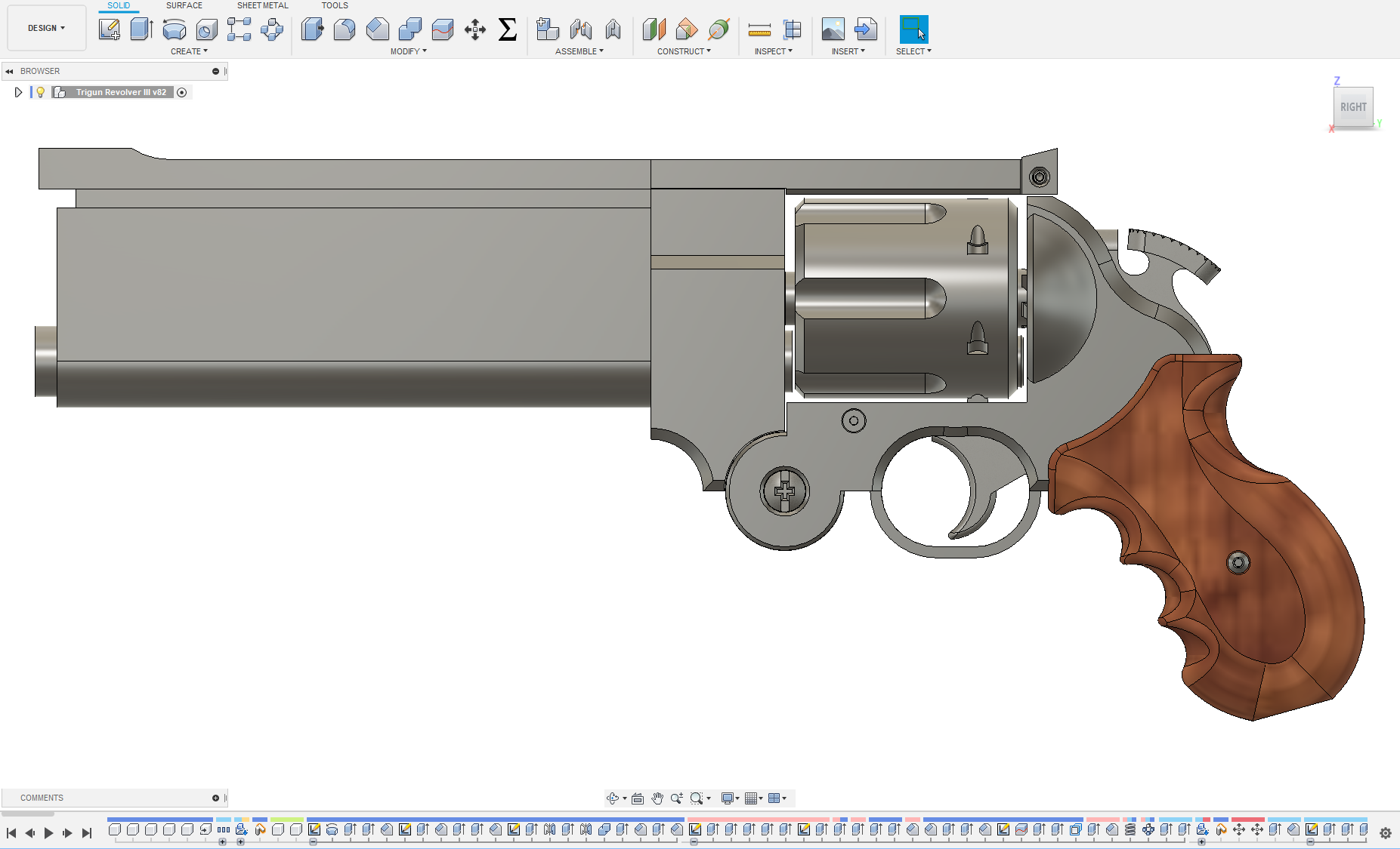
It the Part 1 post for this project, I talked about my search for reference material and took a look at what I found throughout the Trigun Maximum manga. Now, with all that material, it was time to start trying to model the revolver in CAD. With everything discussed in the previous post, about how much the revolver design evolved throughout the manga and all the little detail bits that kept changing, it was going to be a challenge to unify that into a consistent, workable model.
Overall, I had several design goals that I wanted to meet for this project:
- I wanted to have a “functional” replica. No firing pin; I didn’t want to make it able to actually shoot, but I at least wanted the trigger and hammer to work, and the cylinder to rotate.
- I wanted to avoid glue as much as possible in the assembly of this replica. I wanted to use screws, pins, and the like to assemble it. It would make it easier to iterate on the design and replace parts if they broke.
- I wanted it to look as close as I could get to the manga version. Combined with goal 2, there was going to be quite a bit of assembly hardware that I was going to need to hide to give the revolver a clean look without having to glue the pieces together. There is some hardware, screws and pins, shown on the revolver in the manga, but their placement and visibility is not consistent, so I didn’t want to rely on those images to try and place internal components.
Side note for this post: A number of these CAD screenshots are from after I finished most of the modeling, so the details have more or less been worked out already. I didn’t really think to take screenshots throughout the process, too busy thinking about modeling it at the time. That said, my commentary is also probably going to be a little all over the place with regards to past and present tense.
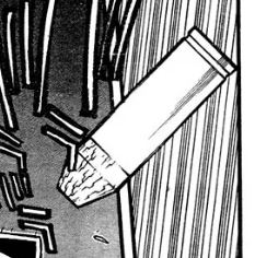
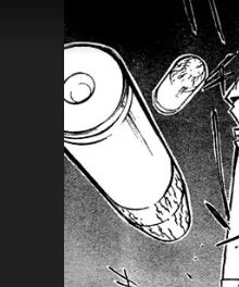
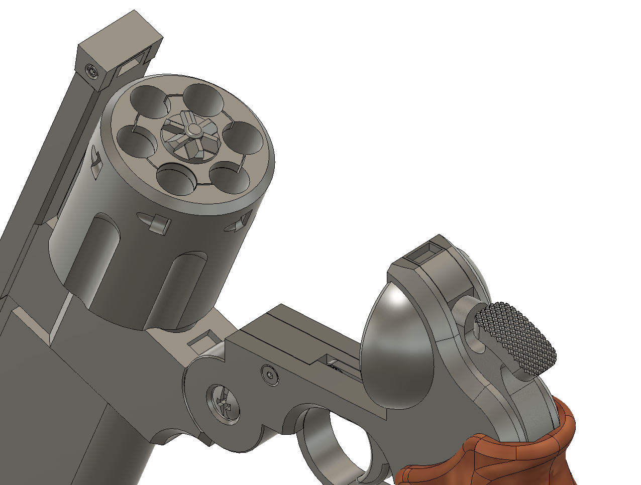
My starting point for this project, was to get the sizing of the revolver correct first. For that, I decided start from the revolver’s ammunition. .45 long colt ammo has standard (or relatively close to standard) dimensions readily available online, and it was easy enough for me to mock up a bullet and casing similar to the manga, based on it’s IRL counterpart. And I say similar, as I ended up extending the bullet casing so it was a decent bit longer than both the manga and the IRL bullet casing. The ones shown in the manga are just far too short for the length of the revolver’s cylinder as it’s depicted. Additionally I made the rim on the back of the casing wider too, so the bullet and casing wouldn’t fall straight through the cylinder with the amount of tolerance I had to add between between the two parts for 3D printing.
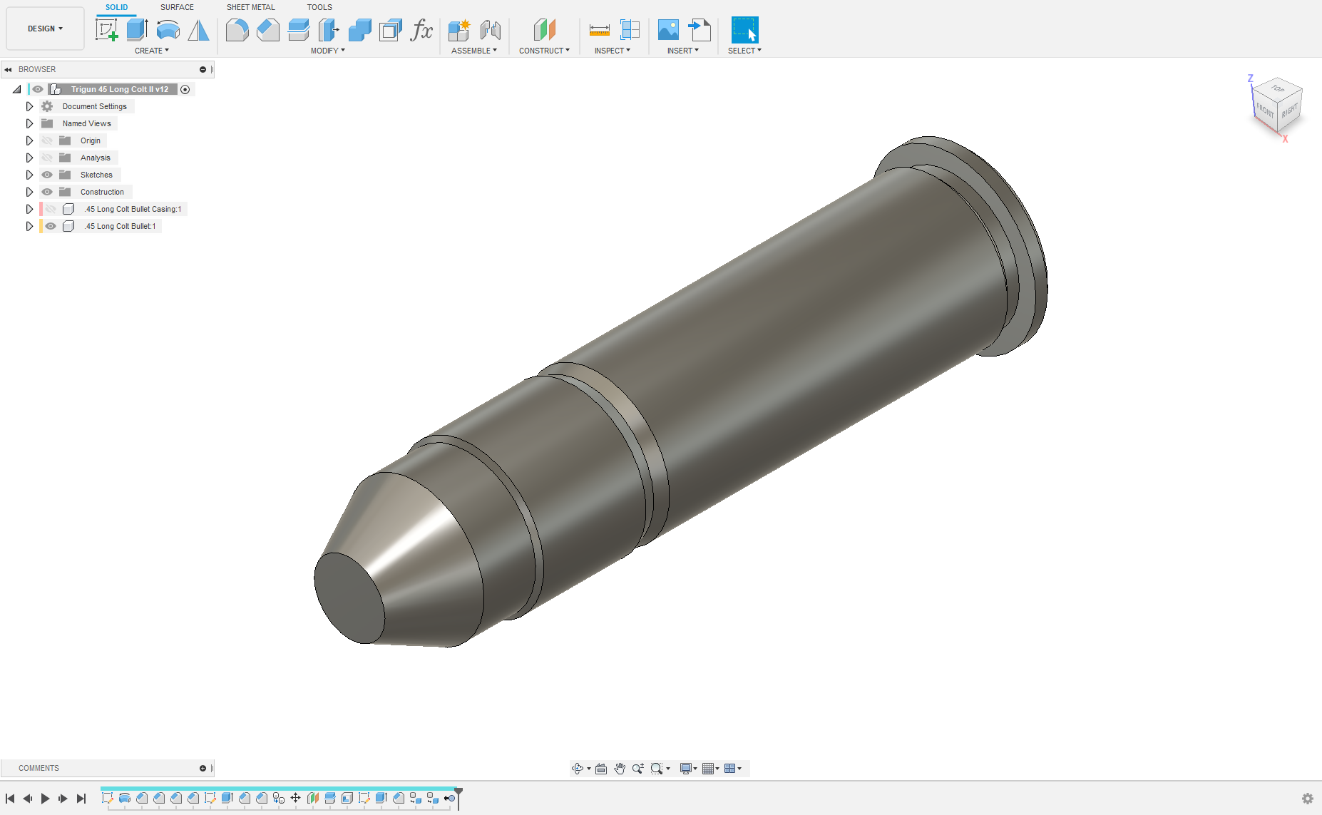
From there, once I had the .45 long colt bullet and casing modeled, I could use that to get dimensions on the cylinder of the revolver and work my way up through the rest of the modeling process from there. Granted, it took a number of tries to get things to look correct, both proportionally, and detail-wise.
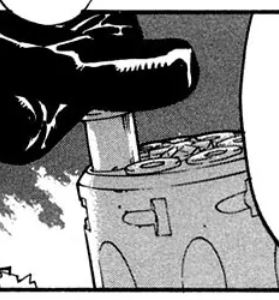
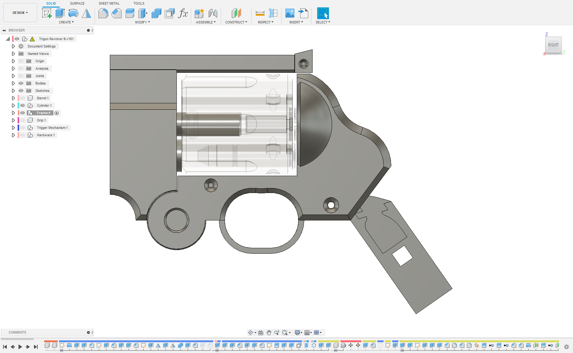
I did have to make some executive decisions throughout this project; the first such in working on the cylinder and deciding which way I wanted it to turn. The direction the cylinder of a revolver turns can be determined (other than actually seeing it turn) by the notches in the cylinder that would catch the cylinder latch (which, in the manga, annoyingly enough, kept changing direction or weren’t even present in most of my references images), those and the ratchet star on the back of the cylinder. Thankfully I had at least one reference image that showed the ratchet star on the back of the cylinder. So, based on that image, watching it’s motion in the Trigun movie, and taking reference from actual revolvers, I decided that on my replica at least, it would rotate clock-wise, and the details on it would reflect that.

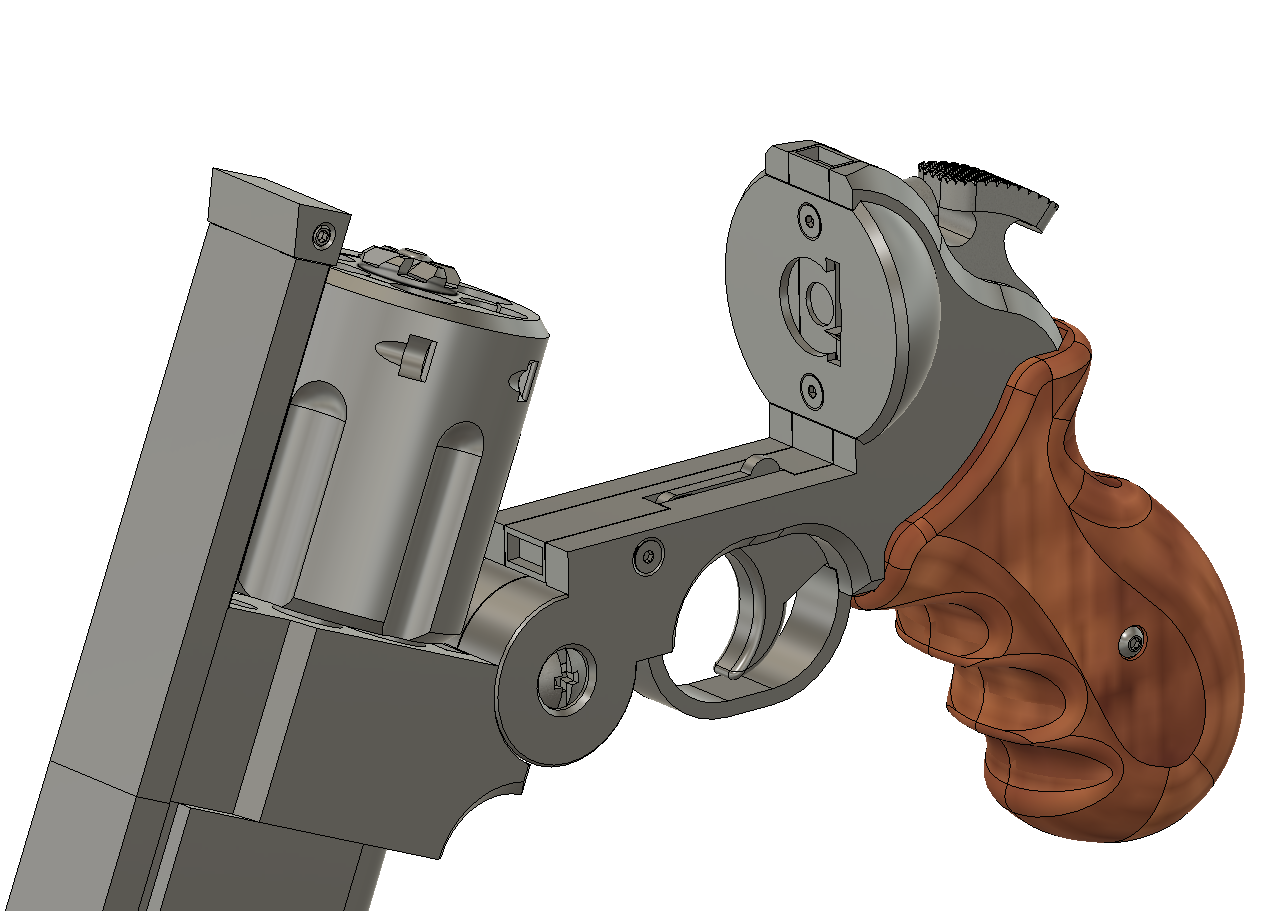
With that decision ironed out, I started work on the frame of the revolver and where the cylinder would sit. The front half of the frame (divided by the hinge on bottom) was the easier of the two parts to design. It just needed to hold the cylinder, have a hole through it for the bullet to pass, and provide a way to align and attach the barrel. The back half of the frame ended up being a bit more complex to model. It had to house the trigger mechanism, the grip would be mounted to it, it needed to meet the hinge on the front half of the frame, and it needed to have the right proportions for a person to be able to reach the trigger from the grip. These were all features that were rather annoying and finicky to get correct, especially combined with the curving geometry of the back of the frame near the revolver’s hammer. It also didn’t help that in the manga, the distances and sizes of these features varied rather widely from image to image at times.
Once I got the shape of it looking reasonably close to the manga, I then had two things to figure out: How to keep it closed, and how to fit a functioning trigger mechanism inside.
After wracking my brain for a while, unable to come up with any good, hidden ways to make the revolver frame stay shut, I settled on using magnets. Two sets of small rectangular neodymium magnets at each point where the frame came together.
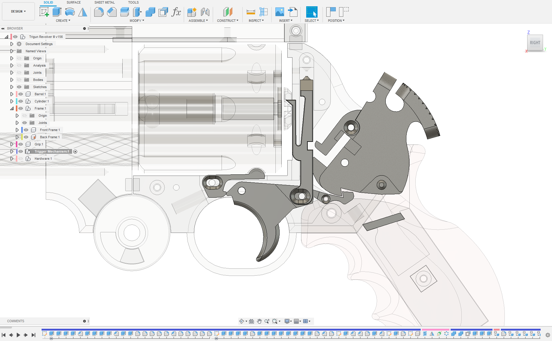
Now as for the functioning trigger assembly, that was going to be more of a challenge. So, to start, I went to work on hollowing out the back frame to make space for the trigger mechanism inside; and to decide out how I wanted to split it for printing and assembly so as to both hide as many of the screws as possible, and still be able to reach the internals for maintenance. In the end, the back frame was split into three plates, a left, a right, and a mid-plate; the left having the hinge as it’s prominent feature, the right plate containing all the holes for the pints and screws for the trigger mechanism, and the mid-plate providing the framing and geometry to keep the revolver rigid while housing the mechanism.
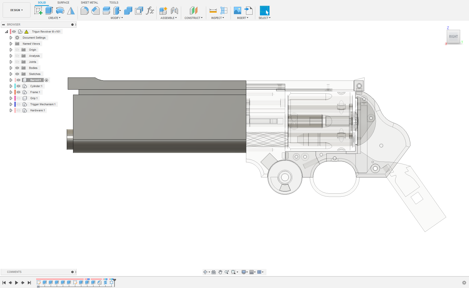
Leaving the frame behind (as there were still many things to consider and it would require redesign and tweaking as I went along), I decided to work on the barrel of the revolver to give my brain a break before tackling more complex parts.
Like the front half of the frame, the barrel wasn’t too difficult to model and the rifling inside the barrel was really where most of my time was sunk into it, trying to get it to look right. The overall length of the barrel, comparatively, is rather comically; with how out of proportion it can seem with the rest of the revolver. I was happy to note that the barrel would not need to be split for printing and would turn out quite nicely as once large piece right off the printer.

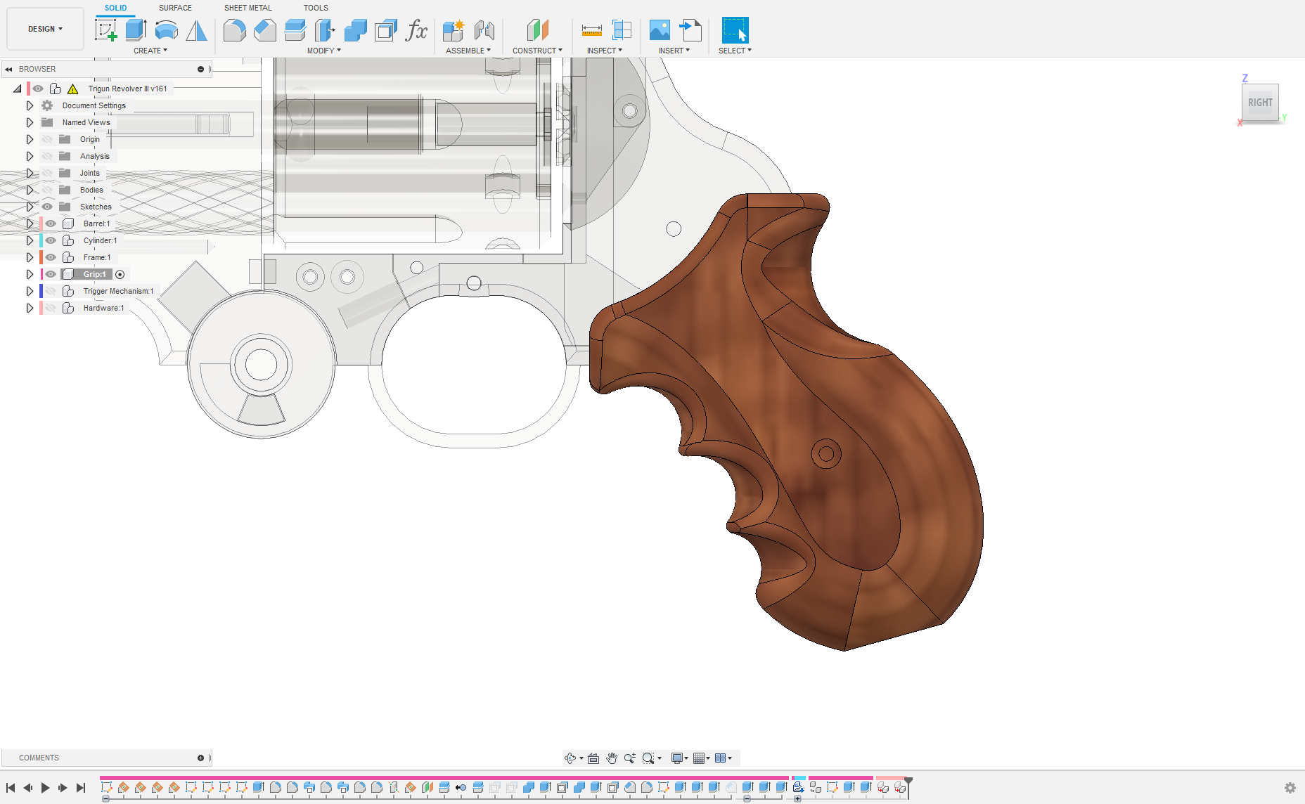
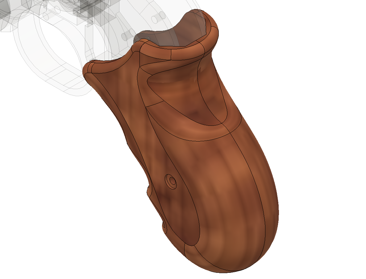
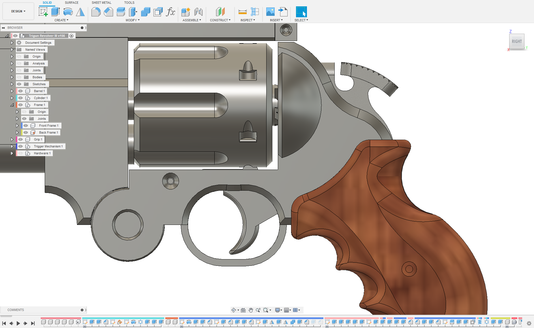
With the barrel modeled, it was time to move on to the grip, the next challenging piece of this model (for me at least). I decided I wanted to try and model it in the style from the first couple chapters of Trigun Maximum. I figured it would be pretty neat to print it using a woodfil filament and then stain it.
Designing the curving features for the finger grips was tough, what with my limited skill in Fusion 360, getting them anywhere close to looking and feeling correct; and strained both my brain and my computer trying to compute some of the features of the model. Granted, with it’s more organic shape, the grip would have been much more suited to being modeled in a program like Blender or Fusion 360’s mesh workspace, but I had no experience with Blender, or modeling with meshes, and decided I was just going to do the best I could, with the workspace I was comfortable in. All-in-all, after a number of attempts, it finally turned out.

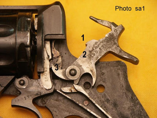
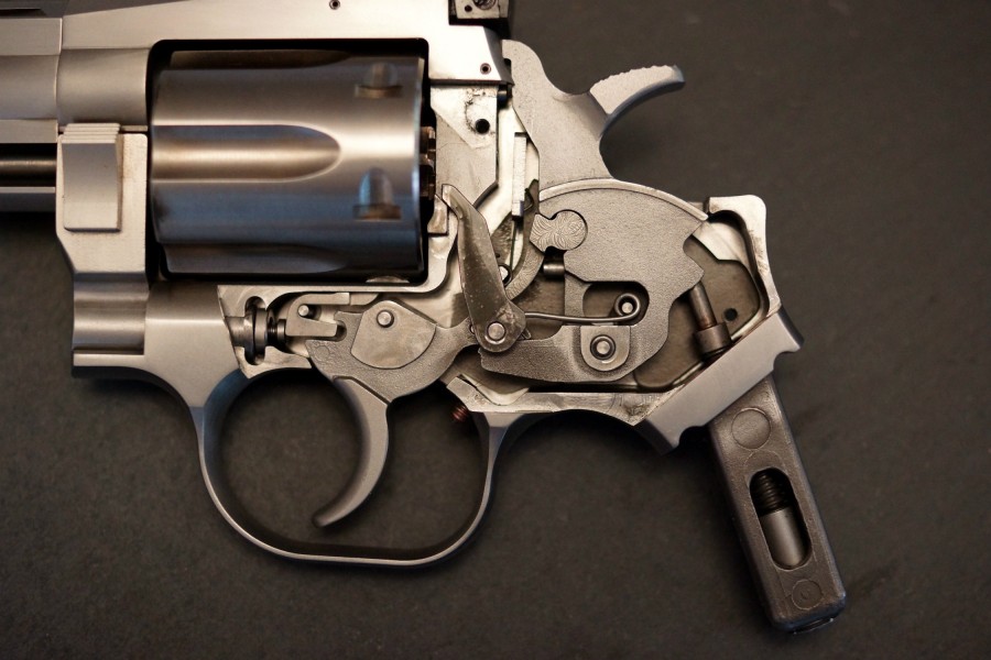
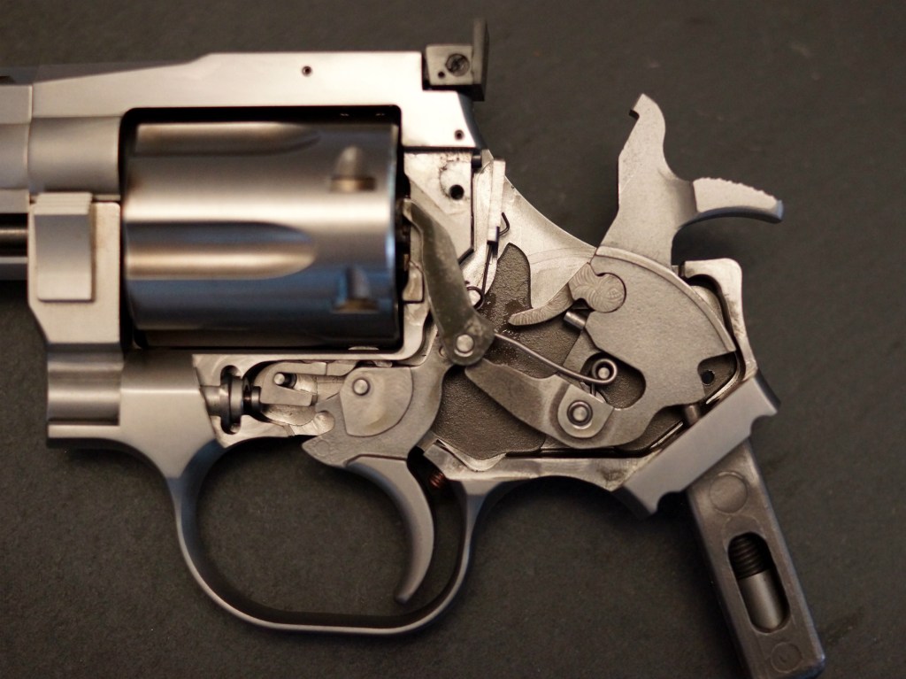
Now, it was time to work out the part of the model I was dreading, the trigger mechanism. As a Mechanical Engineering student I’d decided to take classes more geared toward aerospace and combustion, but now, years later, I was mildly lamenting that I hadn’t taken any classes on cams and gears, and the like. I had no design experience in this area and really had no clue what I was doing. It felt like I’d dove off into the deep end as I started my Googling search for revolver trigger mechanisms and how they worked. Google images and I got to know each other real well as I delved into it’s depths and sat staring at photos of revolver internals and less than helpful disassembly guides.

It took what felt like ages staring at the different designs of revolvers before I slowly started to figure out how each one did what it did. I fleshed out as good as I could manage of a design for the trigger mechanism that would fit within the odd space I had in the back frame of the revolver. It was a rough, very rough, design, and was only single action (cock the hammer before pulling the trigger to fire it). I figured that was the best place to start, just like how revolvers had evolved through history, start simple and slowly work up to a more complex design over time.
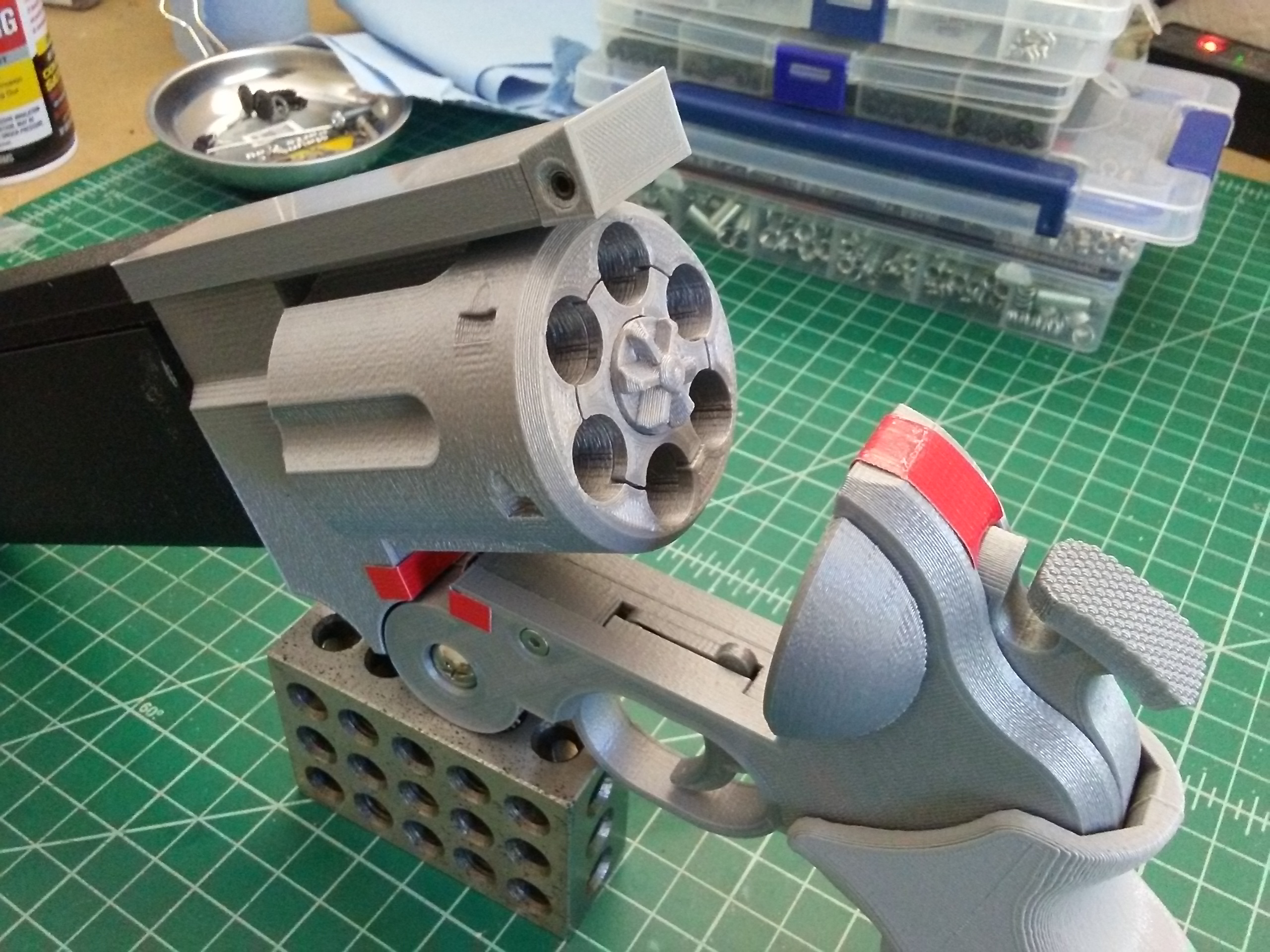
As much as I didn’t want to waste filament, I realized I was going to have to start doing test prints of what I had so far in CAD to make sure it worked how I thought it would. So, it was off to the printer with my first trigger design. I figured I would print just the back frame, the trigger mechanism, and the grip; as those were the parts of the design I figured were going to need the most tweaking and design iterations to get right.
Surprisingly, once it was printed and assembled, I was able to get it to work. It also gave me insight into a number of things I needed to tweak. The grip was one such thing I was going to need to tweak. It felt alright in my hand, but was a big large. I needed to change the curvature on it in some areas and the indents for the fingers didn’t feel quite right in my hand. The other thing I noticed while cocking the hammer, was that the internal part of the frame flexed quite a bit, and I was going to have to add some thing to strengthen it up. So, back to Fusion I went to continue working on the design.
The next iteration of the trigger mechanism, I tried to implement the double action function (pulling the trigger cocks the hammer to fire). In my attempt to emulate existing revolver designs and their geometry, my next test prints didn’t end up working all that well, either binding, or parts of the mechanism not interfacing properly at all. And I ended up back on Google images, trying to search for another design I could cobble together that would be hopefully work.
That said though, I did a test print of the remaining parts, and those came out quite nicely. Vash’s revolver was starting to take shape and was looking pretty good in the black filament I’d been using for my test prints.

Unfortunately for me, with the design of Vash’s revolver, the trigger is rather far forward underneath the cylinder, making it a challenge to get it to interface with the rest of the mechanism in the back frame of the revolver. I need to figure out a good way to overcome this design challenge. And after (what felt like) another eternity on Google images, and trying to wrack my brain for better ideas, I finally ended up trying to emulate the design of the Iver Johnson top-break revolver. It was as simple of a design as I could find that contained the double action mechanism I was looking for, though I was going to have to change the geometry for it work in the space that I had.
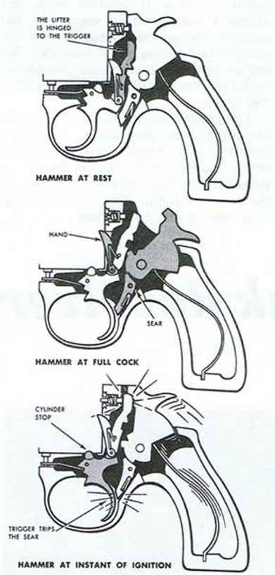
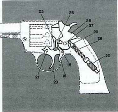
The Iver Johnson top-break revolver design used a transfer-bar (or at least that’s what I’m calling it) attached to the trigger, and a catch, to actuate the hammer and hold it in the cocked position. When the trigger was pulled back completely it would release the catch, allowing the hammer to rotate back into it’s normal position and strike the firing pin.
Since I wasn’t able to get more modern trigger mechanism designs to work, this one seemed like it was my best bet. Implementing my own transfer bar design I was able to get the trigger to actuate the hammer more or less relatively effectively, and there was just enough room to sneak in a small catch to lock the hammer in the cocked position when pulled back manually. Similar to the Iver Johnson design, I was able to modify the trigger geometry to interface with and release the catch to allow the hammer to fall back into place.

This looked like it could work. And hopefully it would work well. In addition to the other tweaks I’d ended up making to the rest of the model, it was really starting to come together into the “functional” replica I’d wanted to make.


Now that I had trigger mechanism that more-or-less worked how I wanted it to (still some tweaking of the timing to be done) it was time to continue with my test prints. After printing out the latest iteration of the back frame of the revolver and my new trigger mechanism, I was pleased to find that it actually worked the way I wanted it to; for the most part at least. It needed some minor tweaking, but overall, I had a workable design finally.
Finally, it was time to start putting it through it’s paces to see where it would break and what parts would need to be changed to accommodate the wear-and-tear of me playing with it constantly in my excitement over my new toy.


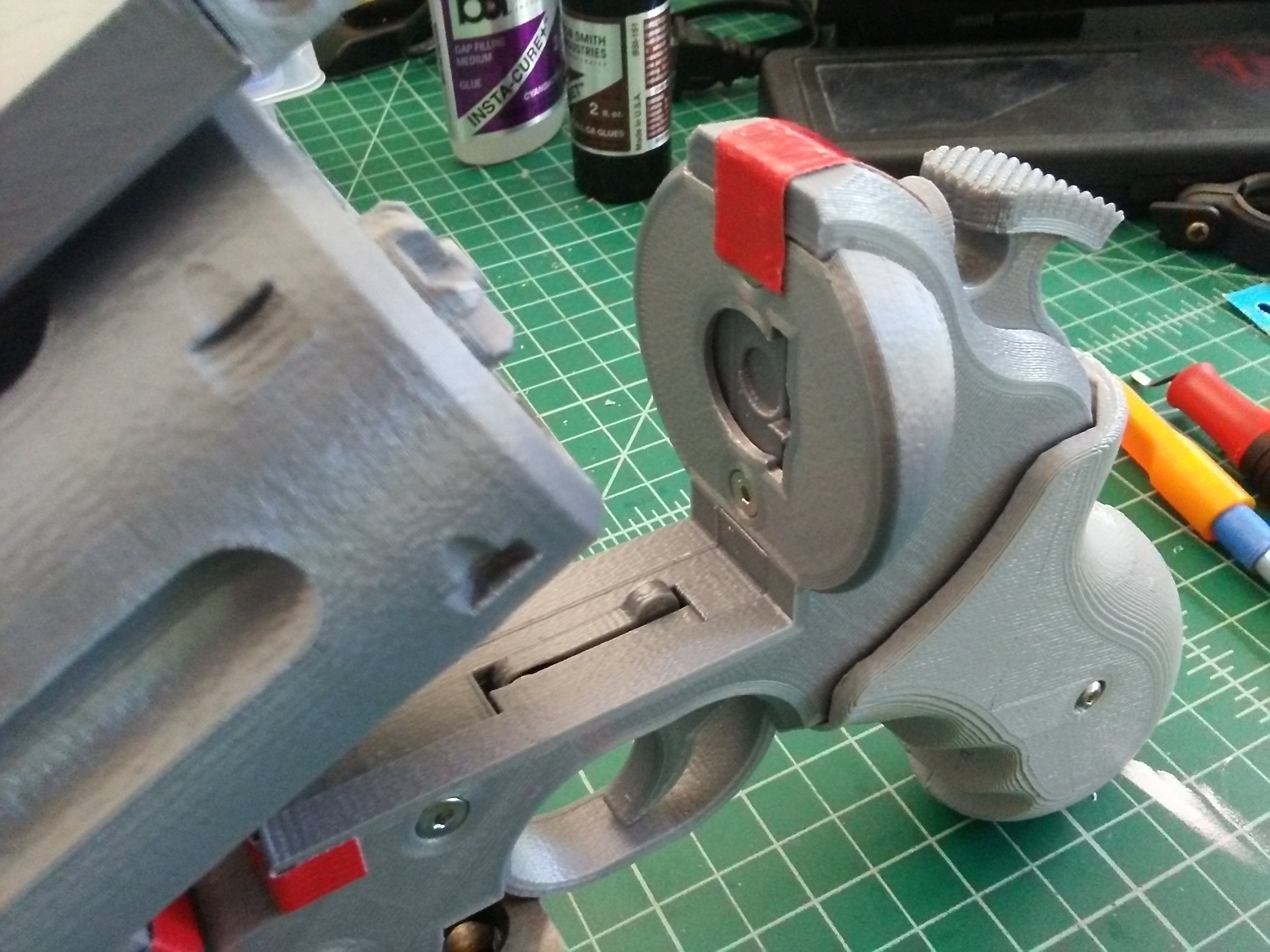
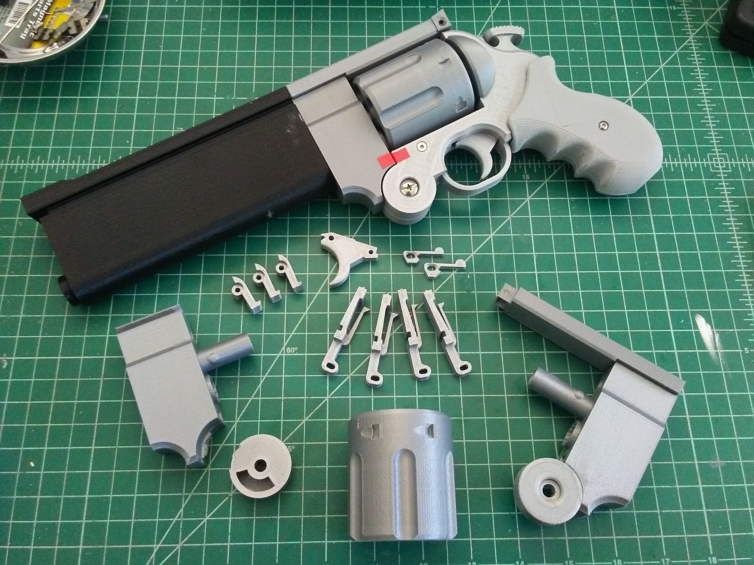
It became apparent pretty quickly that the transfer arm, where it interfaced with the cylinder ratchet and the hammer, was going to see plenty of wear and tear and need replacing with regular use. In addition, I ended up breaking the hinge several times, bent the cylinder stop latch, and even sheared off the post that cylinder rides on. So, the design needed some work, but it was working well for the most part, enough that I was confident in printing out the full CAD model to set it up for display.
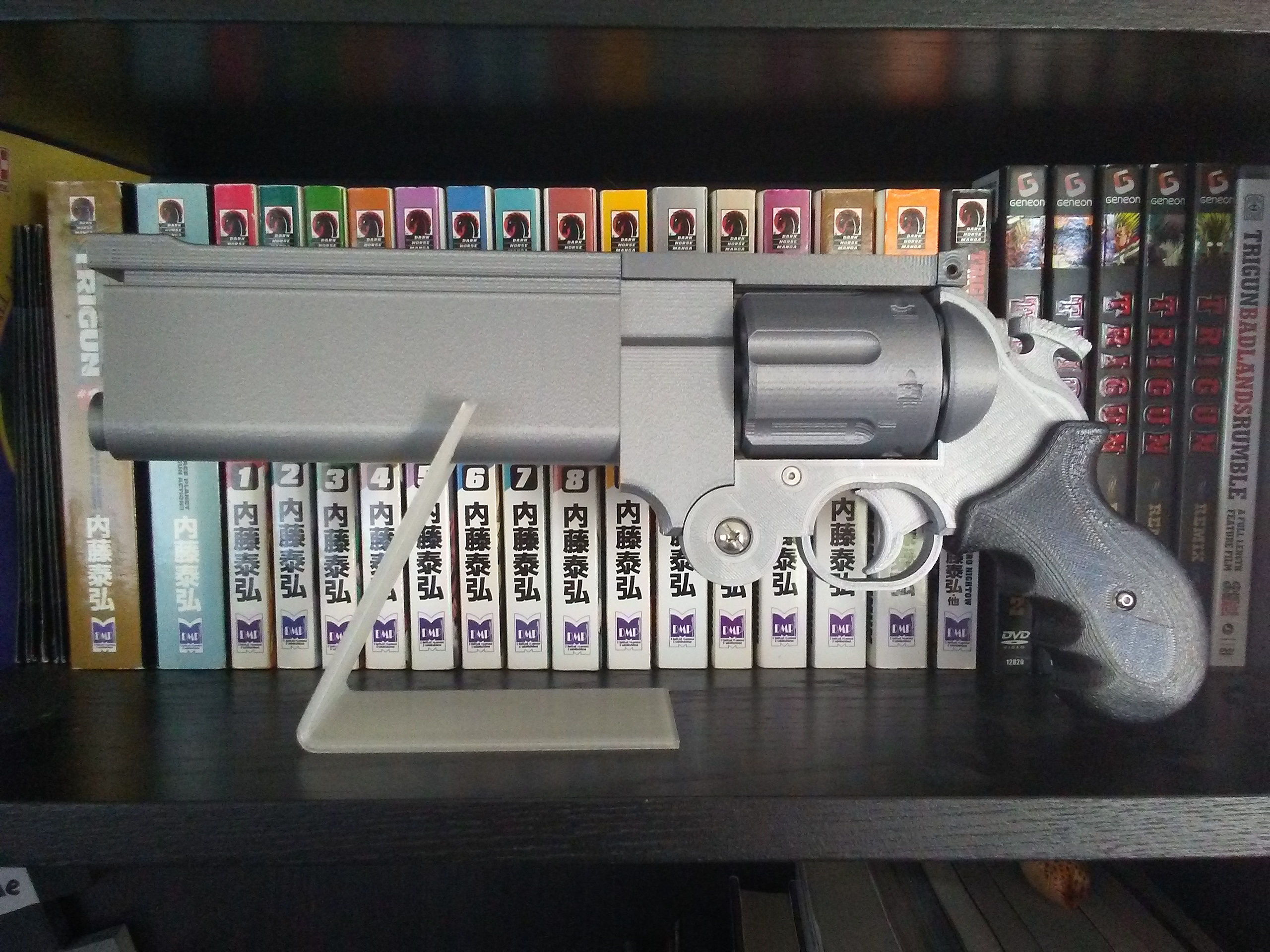
Even with all that work, I am still not done with the design of this thing. For the life of me I cannot figure out a good way to make it have a similar auto-eject as in both the anime and manga, given the space constraints and configuration of the revolver. Additionally, I want to model a set of alternate parts for the grip, the rear sight, and the hammer. Since those parts varied throughout the manga, I thought it would be cool to be able to swap them out depending on where in the Trigun Maximum timeline I was feeling that day. So, plenty more modeling and tweaking things in CAD, along with more test prints to come. But for now, the model is in a good place and I am quite happy with my replica design.
Of course I can’t leave off this post without showing it in action.
And because this is a replica, and I don’t want anyone mistaking that fact if it ever leaves it’s shelf, I designed a bright orange cap to plug the barrel. Safety first kids!

Not sure what the next post for this project will be, I definitely will have more to talk about as I continue to modify the design, and model those alternate parts for it. I also want to paint and weather it, so not sure what will be next, but there will definitely be more to come!


Hey! Any updates on this? I’d love a working replica, I got started on one myself but also stalled out when it came to the auto eject function.
Hey, thanks for the comment. Unfortunately no real update on it. I have it sitting on my display shelf (broken from my playing with it too much) and I keep looking at it and thinking about how I need to revisit the project (and reprint parts of it). I haven’t had any new ideas that would work well for the auto-eject either. It’s a tough conundrum with the placement of the barrel getting in the way of any of the ‘traditional’ auto-ejects for top-break revolvers. I have toyed with the idea of just leaving out the auto-eject in favor of just calling the thing as complete as I can get it and then seeing about cleaning up the files for release, but I haven’t committed yet. Your comment has gotten me thinking about it again, so maybe it’s time I actually put some effort into revisiting the project.